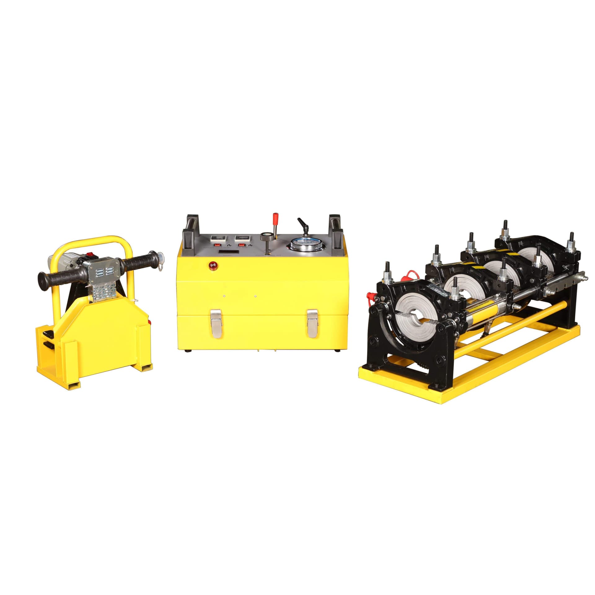
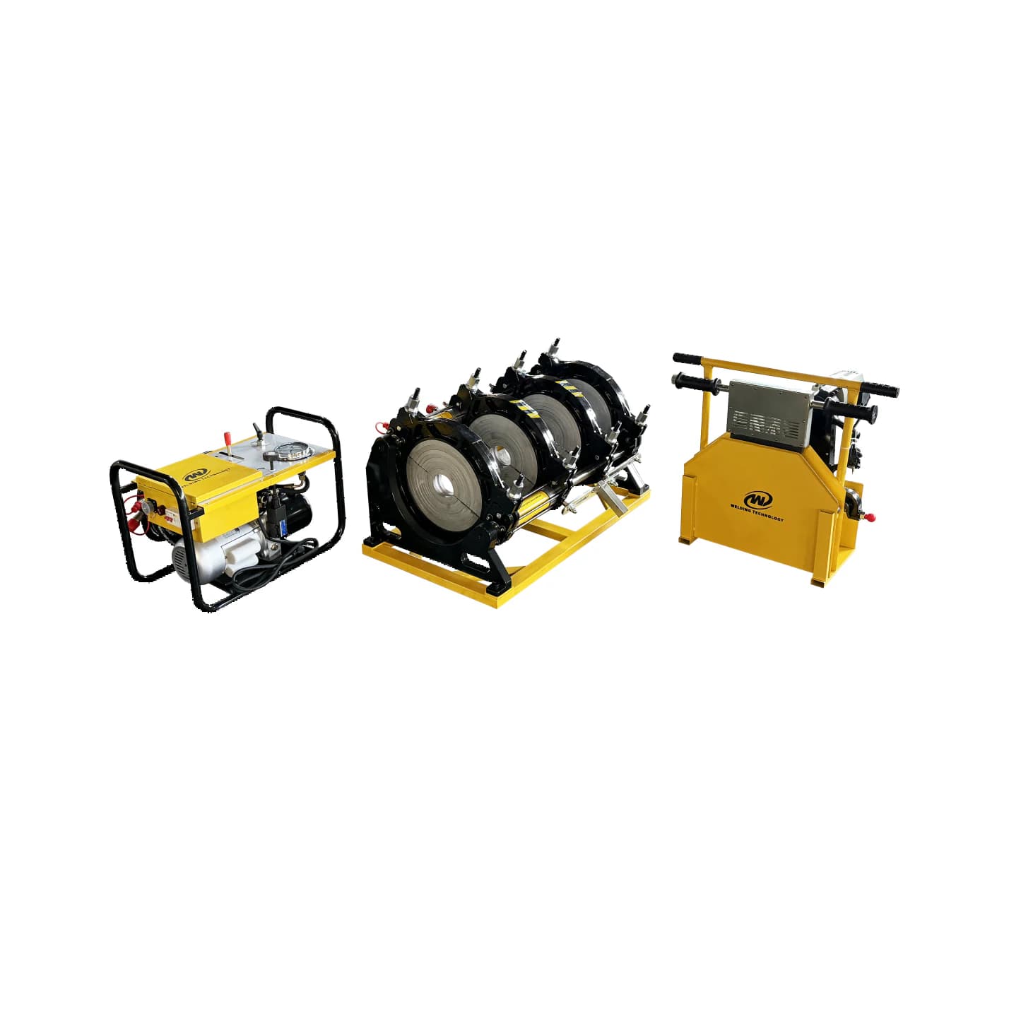
A linked set for facing, heating and pressing
The WD315A product description names a basic clamping frame, electric facer, heating plate and hydraulic unit. The frame holds the pipe ends in alignment while the tools prepare and heat the joint faces. The hydraulic unit then provides the controlled movement and pressure required by the selected procedure.
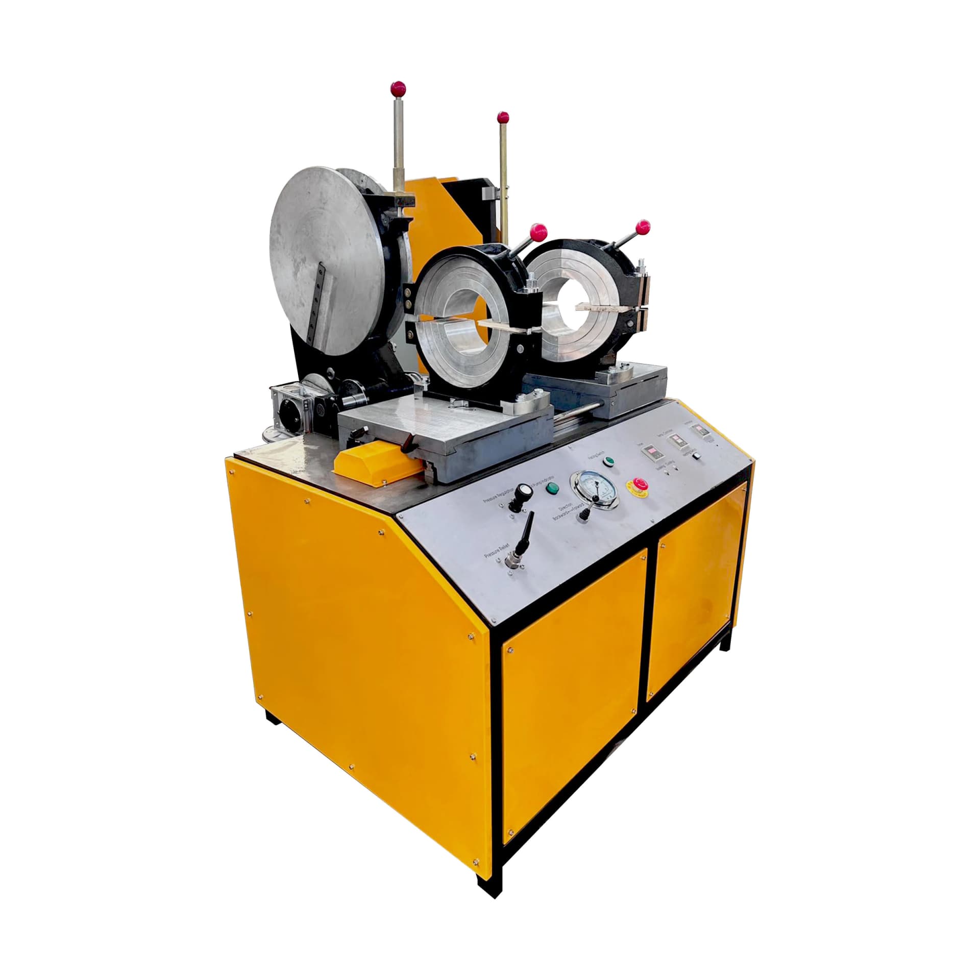
The manufacturer overview photograph shows these separate assemblies together. The control close-up identifies temperature and timing displays and a pressure gauge, helping a buyer define the instruments and records required for the job. These are manufacturer product images, without a claim of GLOBSEEK inspection or ownership.
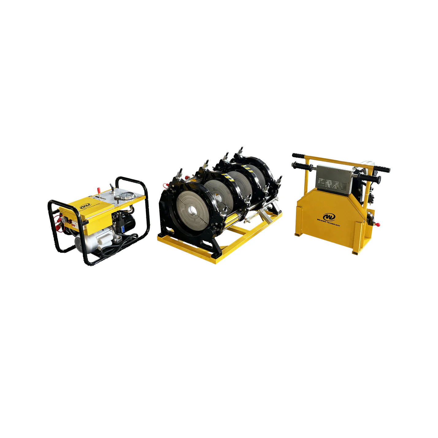
WD315A manufacturer product photograph showing hydraulic unit, clamping frame and facer/heater support. Reference equipment arrangement.
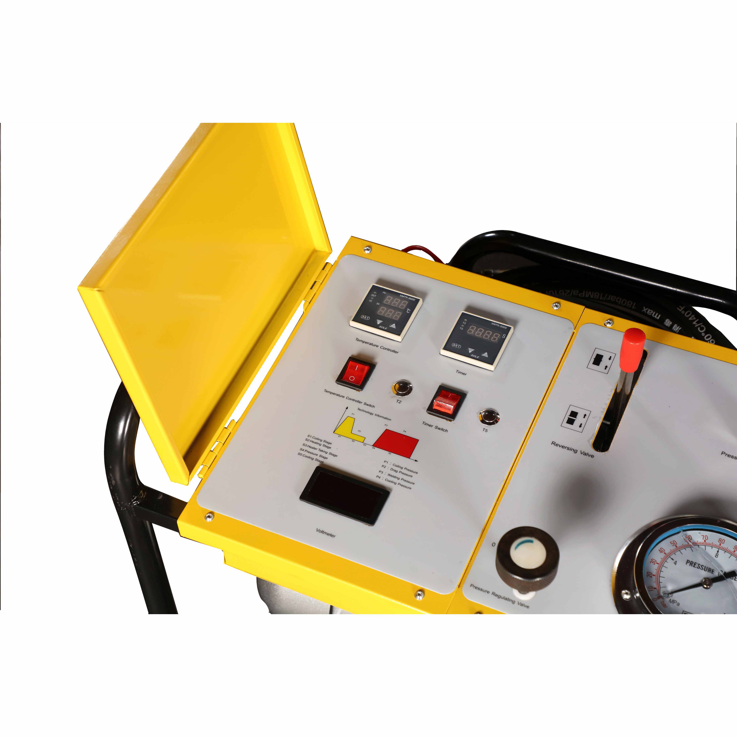
Manufacturer close-up of WD315A hydraulic-unit controls, temperature display, timer and pressure gauge.
Confirm diameter inserts and the pipe combination
The published diameter list runs from 90 through 315 mm in specific steps. Confirm the supplied clamp inserts for every required size, together with pipe material, wall thickness or SDR and fitting geometry. A maximum diameter alone does not settle whether the intended job can be clamped and processed.
The official page lists HDPE, PP and PVDF applications, but that material list does not supply the project fusion parameters. Agree the applicable jointing procedure, heater condition, pressure calculation and acceptance method with the pipe system specification. No cycle time or welding-temperature setting is inferred here.
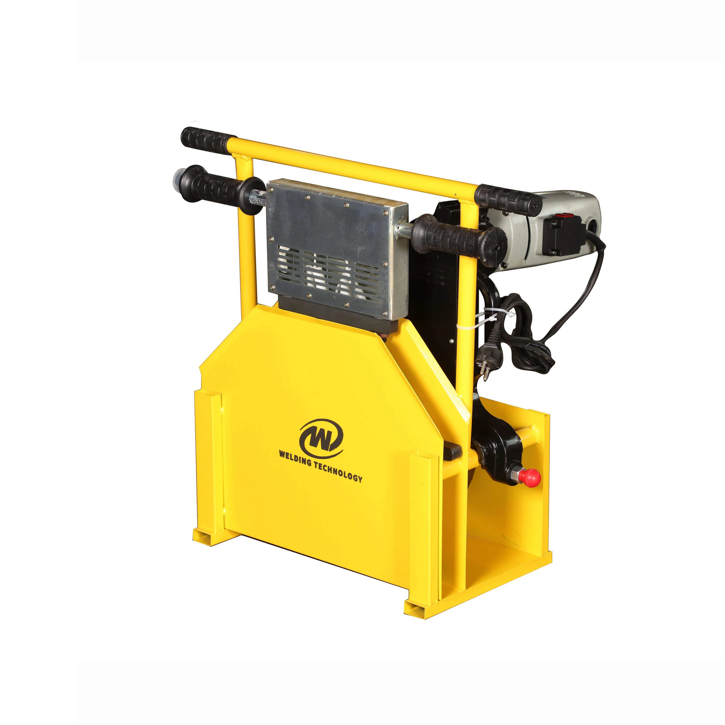
Manufacturer WD315A detail photograph showing the electric facer and heating-plate support.
Define power, instruments and the quotation scope
The published power total is 5.35 kW, comprising the 3.5 kW heater, 1.1 kW facer and 0.75 kW hydraulic unit. Check the site supply, cable length, generator arrangement if used and the actual electrical connections against the supplied equipment schedule.
The manufacturer separately lists a digital heating plate, flange or stub-end holder and data logger as options. Include any required timer, gauge calibration, recording format and handling supports in the quotation rather than assuming every pictured or optional part is standard.
Planning your configuration
- Send pipe outside diameters, material, SDR, fittings and site power details. Request the exact inserts, component list and operating documents for the offered revision.
- Confirm the fusion-data and joint-acceptance requirements, instrument calibration and any data logger or flange holder. Manufacturer certification and warranty statements require documents for the actual offered build; they are not independently verified in this reference.
Manufacturer sources
Product information and images are based on the following manufacturer references, reviewed on 2026-10-20.