
Plan the electrode survey around the investigation
The WDDS-3C measures the voltage response to current introduced through ground electrodes. Apparent resistivity is interpreted with the electrode geometry, so an instrument selection starts with the investigation target and available survey area rather than a promised detection depth.
For groundwater or engineering work, define the intended array, line length, electrode spacing and access restrictions. Request the acquisition and interpretation workflow appropriate to those conditions, including the checks used to recognise poor electrode contact and electrical noise.
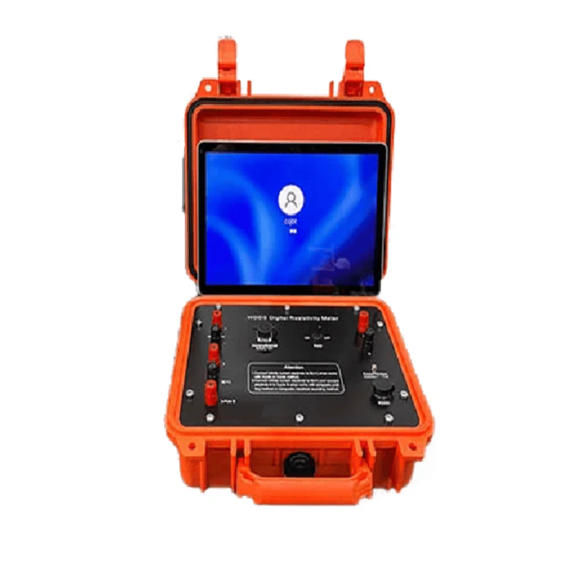
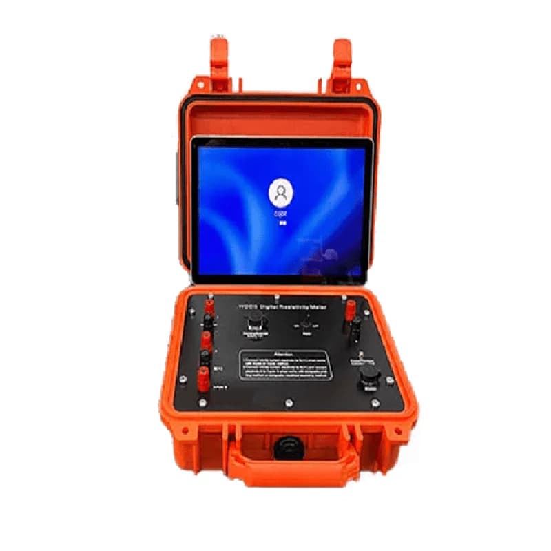
Geotech host illustration on the WDDS-3C product page. Tablet and host configuration should be confirmed with the quotation.
Keep the internal supply distinct from external power limits
The manufacturer lists built-in high-voltage choices up to 200 V, with a 300 mA maximum current. These are different from the page’s external transmitter limit and should not be combined into one assumed operating point.
Confirm the proposed current source, batteries, cables and duty cycle for the expected ground resistance. The receiver input range and self-potential compensation describe measurement capability; they do not establish a target depth or guarantee that a geological boundary will be resolved.
Agree the complete field package and data handover
The gallery also shows a WDDS-family accessory arrangement with cables and electrodes. It is useful for identifying the components to discuss, but does not establish the quantity or type supplied with every WDDS-3C.
List the electrode materials, cable lengths, connectors, battery charging arrangement and carrying cases in the order schedule. Confirm data export, software licence and field training, and request a demonstration that produces files in the format required by the interpretation team.
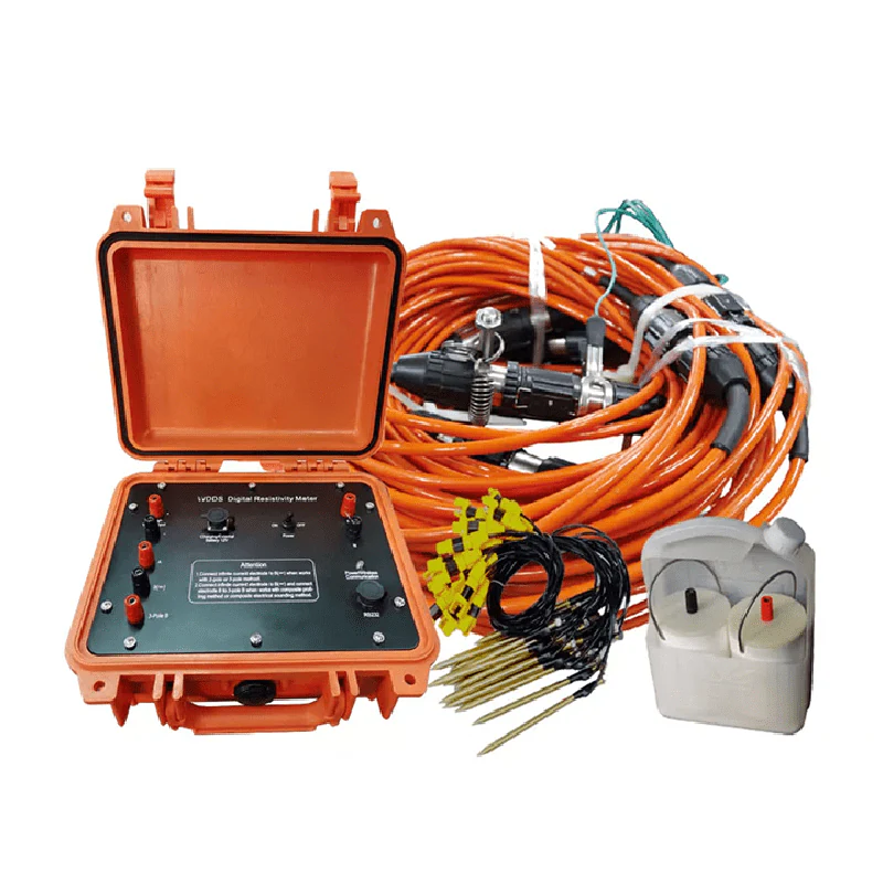
Geotech WDDS-family accessory illustration from the WDDS-3C gallery. Exact host version and all kit contents require confirmation.
Planning your configuration
- Provide survey objective, target geometry, available line length, electrode spacing and site electrical conditions. Specify the power arrangement and required software separately.
- Do not convert transmitter ceilings into depth claims. The manufacturer page contains inconsistent battery wording, so only the clear internal-HV and external-supply entries are reproduced; confirm the actual battery build.
Manufacturer sources
Product information and images are based on the following manufacturer references, reviewed on 2026-10-20.